LC-1 wide band oxygen sensor install

Ducati Forum

Help Support Ducati Forum:

Joined
Jun 11, 2012
Messages
288
Location
Nz
I have just finished installing 2 LC-1 wide band O2 sensors to compliment my TuneBoy setup. Wideband sensors will be necessary for many tuning options not just the TuneBoy. There was a bit more to it than I had hoped so I'll leave some bread crumbs here for anyone that wants to follow down the same path.

The main thing I think I hoped to avoid was removing the exhaust system - but that ain't going to happen so just get on with it, it's not a big deal.

You will be taking off the mid and lower fairings, the tank, and lifting the seat sub-frame, then taking off the exhausts so make sure you have the right tools before you start !

A couple of tools to note are:
  1. a Torx T40 for the sub-frame bolts and on the left side this will need to be turned by a long reach extender with a swivel or universal drive.
  2. a ball headed 6mm Allen wrench for the rearward exhaust bolts which are somewhat inaccessible.

Procedure:
  1. Remove mid and lower fairings & Seat.
  2. Remove the tank. There is a dry connect in the tank/airbox space and breather at the front right to disconnect.
  3. Remove or completely loosen the lower bolts holding the seat sub-frame using the T40. Now pivot the whole sub-frame into the air and ensure there is enough tension in the top bolts to hold it there.
  4. Remove bolts at front of silencers 8mm head, 10mm nut (hold with a 3/8 swivel drive).
  5. Remove the larger bolts holding the rear of the exhaust. 8mm cap screw with 6mm Allen drive. If you use a ball head Allen here then you won't need to remove the left hand rearset, otherwise you do.
  6. Remove the springs holding the silencers near the flapper valve. Spray some CRC on the slip joint then wiggle the silencers off.
  7. Remove the other springs from the exhaust headers. Spray some CRC on the slip joints. Now the flapper valve section kind of rotates and stretches away from the front header and the rest follows easy.
  8. Unhook the standard sensor wiring and remove the sensors.
  9. MAKE SURE YOU HAVE PERFORMED ANY 'FIRST POWER UP' OR 'FREE AIR CALIBRATION' ROUTINE AT THIS POINT. YOU DO NOT WANT TO FIND THAT HAVE TO COME BACK HERE RIGHT AFTER YOU HAVE JUST TIGHTENED THE LAST SCREW ON THE FAIRINGS !!!
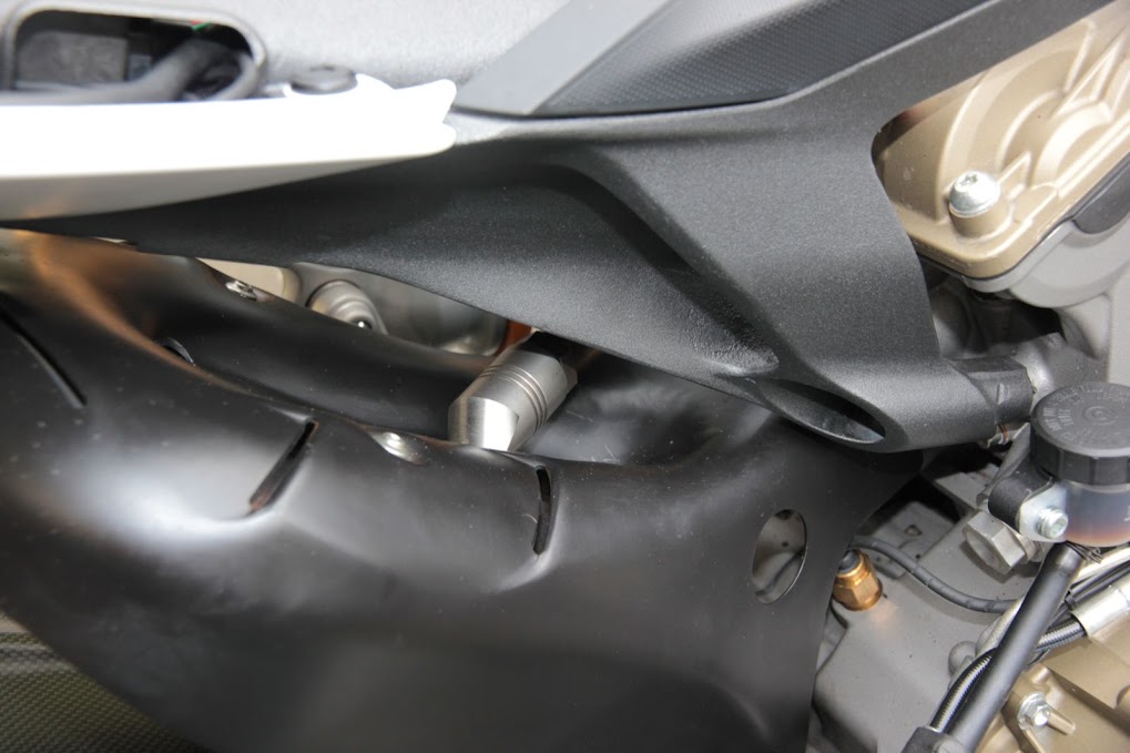
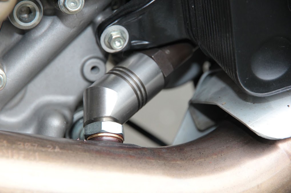
  10. Put some high temp thread lube(something like Coppercoat) on the threads and fit the wide bands to the header tubes. (You will need to loosen/remove the heat shield from the loop tube)
    IMG_5357.JPG
    IMG_5358.JPG

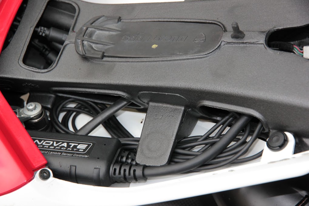
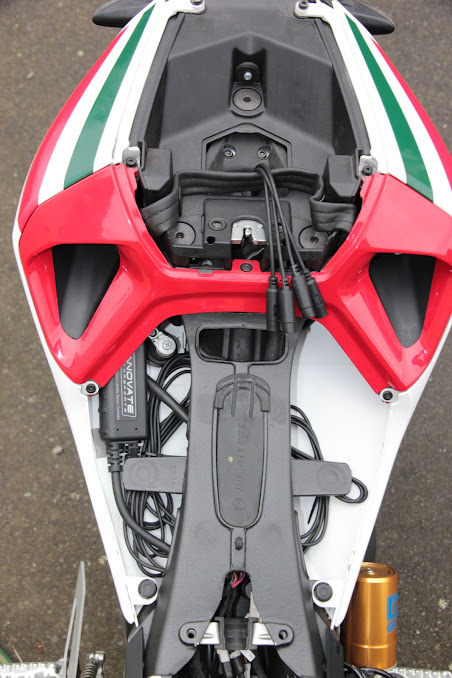
  11. Reassemble the exhaust system and lower the seat sub-frame. The rear sensor cable passes underneath the BBS unit and through the rear right opening in the sub-frame and past the seat lock mechanism.
    IMG_5355.jpg

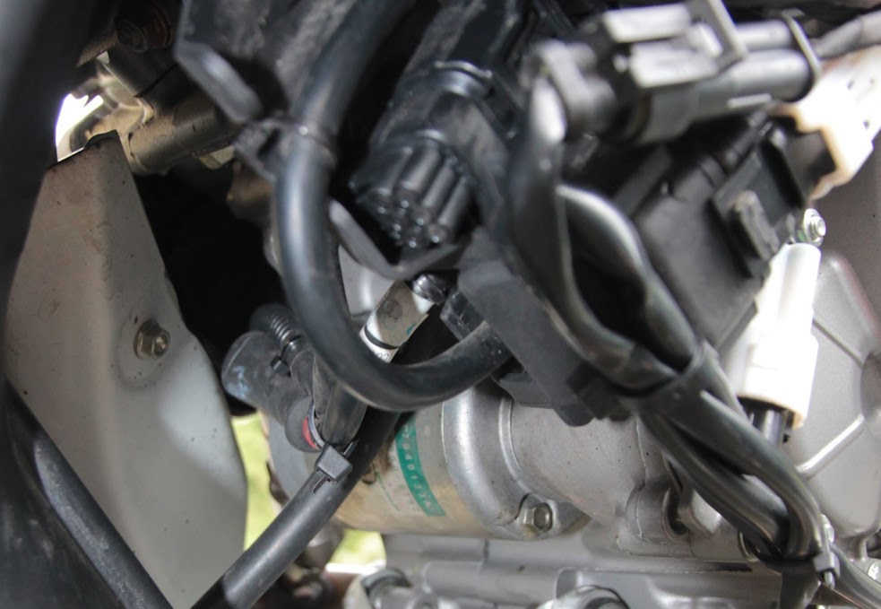
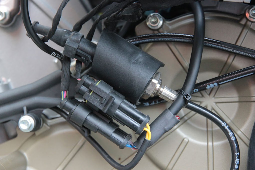
    The front sensor cable runs adjacent to the starter motor cable and cab be cable tied there for support.
    IMG_5359.jpg

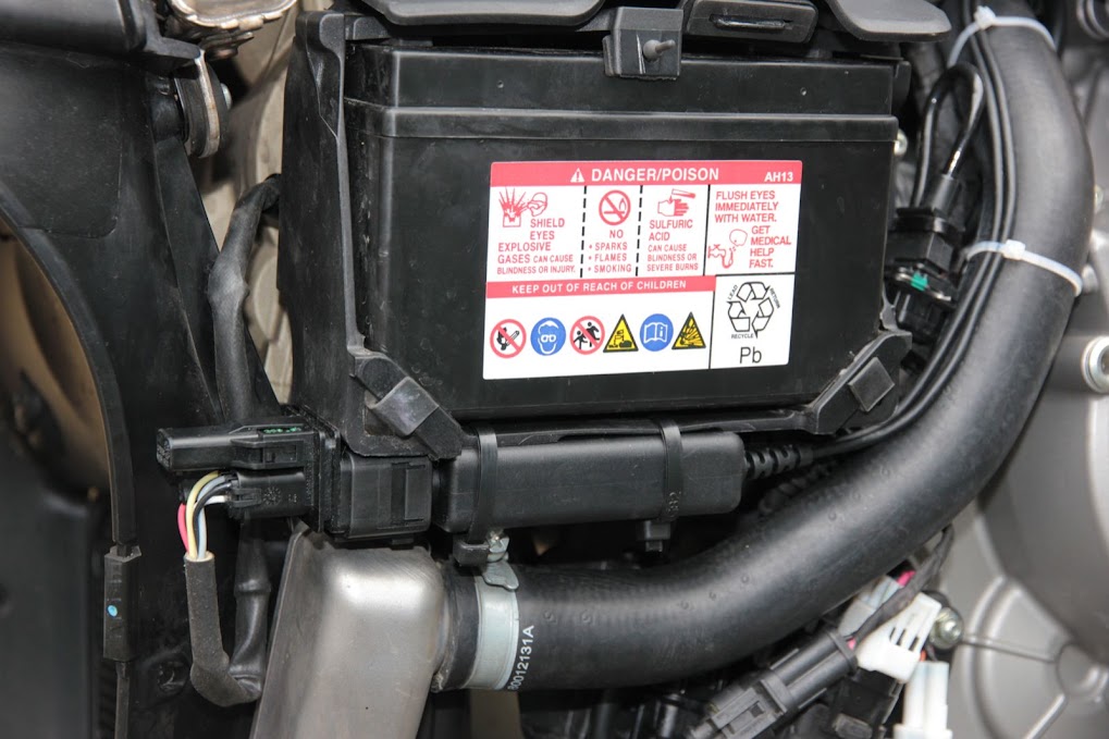
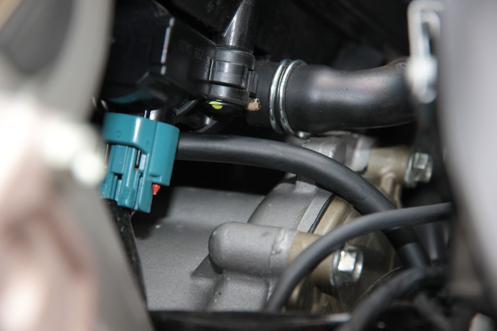
  12. Cable tie the front controller to the bottom of the battery box and run it's output cable through the 'V' between the cylinders.
    IMG_5360.JPG

    (It's a bit of a wiggle in the dark but you'll find the right way before long).
    It should come out on the right side of the bike just in front of a green connector.
    IMG_5353.JPG

    The serial port wires can be cable tied to the coolant hose and run up to the back of the bike under the BBS and come out with the diag connector. (Extra length can be stored a coil under the seat area.
    IMG_5361.JPG

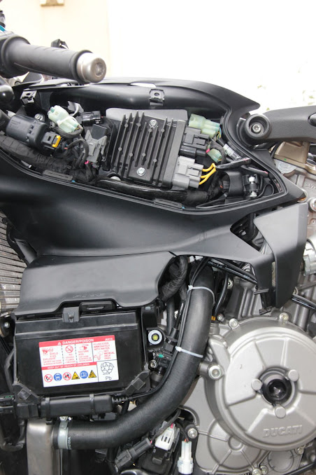
  13. The electronics housing needs to be removed to gain access the the front connector and the ECU must first be removed to gain access to the third screw retaining the electronics enclosure!
    IMG_5350.JPG

    The cable for the front controller should be supported with a cable tie to the 'hydraulic sensor thingy' just above the connector.
    IMG_5351.JPG

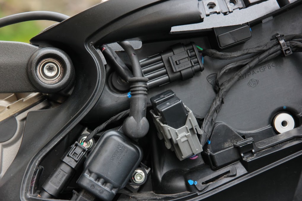
  14. The rear controller fits nice enough under the right side of the seat with the output cable running forward through the sub-frame in the original cable cleat and into the electronics housing. A little sticky foam tape will stop it rattling around in there.
    IMG_5362.JPG

  15. if you are using an OT-2 then it fits nice under the seat cowl.
  16. put everything back, ride, tune, & be happy !

Some photos from my install may be of use....
LC-1 install photos on picasa

Good luck and happy spannering...
:)
 
i just got 2 LSU4 sensors put on the desk...

but i guess i will have to go with the whole package...

THANKS a lot!
 
@pouakai,

I would love to hear what you're trying to achieve by installing the sensors. I assume this is in conjunction with the tuneboy reflash? Is this only necessary if you don't have access to a dyno and tuner?

Thanks for the write up!
 
My theory is that the factory tuning no matter how much improved from version to version will always be compromised by need to meet emissions regulations. This is really only obvious at low throttle openings and this is my last bugbear with the bike - right now I'm like 98% satisfied, fix the low end stutter and I'll be 100%
The wide bands are necessary for any 'roll you own' tuning especially Dyno tuning. Without you rely on the tunes generated by others.
P

does that work with the Tune Boy software? and will you be able to see and log AFR in same software?
Thanks
 
Digging out the old thread to realize I need 2 kits. Damnit.

Will get the 2nd one from innovate...
 
Did you install any visual display or only using them for laptop feedback? Are they powered under normal riding or only tuning? It drastically shortens the life span of the sensors to either power them when they do not have exhaust flow across them, or to run exhaust across them without the heater circuit active.
 
I wanted to revisit this thread. The wideband sensors that come from Tuneboy now ship with the updated Innovate controller; the LC-2. Wiring and form factor seem a bit different. The good, the controller seems smaller. The bad, there's a LOT of f'n wiring.

See pic. The longest cable there is eight feet. For a motorcycle. There are two of them. Plugs seem way larger than necessary, but that is a OE Bosch thing.

Updates to follow...
 

Attachments

  • IMG_0991.jpg
    IMG_0991.jpg
    95.6 KB
I've read that you can't modify the cables (trim to length) and that it effects the signal. Can anyone confirm or deny this?
 
Which cable in particular?

I thought about altering the cable, the longest one which runs from O2 sensor plug to controller input, but I couldn't find my 9V battery to power up the multimeter to check the pins. They do make shorter cables a three foot one, for $30 each.

I would have rather had that from the get go.

Right now I'm thinking about routing the O2 sensors cable to the left side of the bike and mounting everything under the battery, and routing the controller output cable, which connects to the bike's O2 sensor inputs on the main harness, between the radiator and horizontal cylinder.
 
Holy .... what an epic pain in the ass. I'm just leaving this trail of breadcrumbs for anyone else who is unfortunate enough to buy two wideband kits and install them and run into the same wall.

So when you buy the WB kit from Tuneboy, a plug matching that of the OEM NB O2 sensor is included. The idea is that you plug the controller into the main harness, and the WB O2 into the controller. Seems easy.

I do all of that, get everything packaged away nicely...even the ridiculous 8' cable. Before auto tuning I did a high speed log to make sure it was capturing good data. The problem was is that the Tuneboy Trim program was seeing my A/F ratio at something ghastly like 10:1. Bike runs fine though. It was almost like the Trim program was seeing the O2 sensor output as if it were a narrow band sensor, which it wasn't.

I re-read the manual and begin double checking things.

I check the plugs and notice the brown wire (analog 2) is fed into the main harness, not the yellow wire (analog 1). I had to go buy a serial adapter for this next part...and why the F is anyone still using serial connections? Its 2015...but anyway. I plug in the serial output of the controller into my laptop and fire up the LM Programmer software. This allows you to view and set the parameters of the controller. I discover that analog 2, the brown wire, is setup to look like a narrow band sensor. So at 13.2:1 there is just under 1 volt being fed upstream. Now, because the Trim program was thinking this was the sensor output of a WB sensor, it interpreted this output as something like 10.0:1. If you've seen one of those voltage charts for narrow band sensors, like I've attached below, it will make sense.

The solution. Using the LM Programmer, I was able to change the parameters of the analog 2 output to match what a WB sensor's output would be. Fired the bike up and now the Trim program sees a nice 13.2:1.

FML.
 

Attachments

  • NB Chart.JPG
    NB Chart.JPG
    20.4 KB
  • WB Chart.JPG
    WB Chart.JPG
    27.6 KB
Last edited:
Which cable in particular?

I thought about altering the cable, the longest one which runs from O2 sensor plug to controller input, but I couldn't find my 9V battery to power up the multimeter to check the pins. They do make shorter cables a three foot one, for $30 each.

I would have rather had that from the get go.

Right now I'm thinking about routing the O2 sensors cable to the left side of the bike and mounting everything under the battery, and routing the controller output cable, which connects to the bike's O2 sensor inputs on the main harness, between the radiator and horizontal cylinder.
Correct, I was thinking the O2 sensor cable. I was watching a video article on a/f ratio meters and it mentioned that most are not designed for specialty fuels like ethanol etc, some of which have richer a/f ratios but the meter is thinking gasoline and giving out incorrect readings. I must find the video and share the advice.
 
I left the O2 sensor cables alone, but I did shorten the 8' cable tonight. An epic pain in the ass...again. Some of the wires are shielded inside the outer jacket, so you have to work with that. I've included a pin diagram below. Some of the pins on the controller side connect to more than one. There are also two yellow wires. ;) My advise to anyone who tries to do this is to take your time, use solder connections and individually heat shrink them, and heat shrink the whole thing. You should have plenty of the aluminium shielding to wrap around the protected wires. Basically, all the ones other than red or blue. Which I suspect are the heater circuit wires.

The stoichiometric A/F value is different, even between gasoline, E10, E15, and of course E85. The E85 has to run super rich, and obviously each is more progressively enriched as ethanol is added.

There isn't a gas pump around here that doesn't read "may contain up to 10% ethanol". After I work all this out and may try a trim table using values for E10 and see how the bike responds. Obviously, back to back dyno testing would be the way to go.

A lambda of 1.0 is always where given fuel is stoichiometric. Through the Logworks program, you can actually change A/F ratio which matches the stoichiometric value of the fuel you are using; it defaults to 14.7:1. I suspect this is so you can setup a narrow band type sensor and use that narrow target range for different fuels.

From what I can tell, the Trim program is using A/F values, not lambda. So if one were to know where 10% ethanol gas produced the most power, this could be accounted for. I can't remember where I got this chart from, but it was within a pretty detailed word document about the differences of ethanol blended fuels.
 

Attachments

  • Lambda.JPG
    Lambda.JPG
    64.2 KB
  • Plugs.JPG
    Plugs.JPG
    18.1 KB
Last edited:
I am running an Akrapovic Full exhaust with Tuneboy. I purchased two LC-2 controllers and started stripping my bike in preparation for the install.

The first problem i ran into is the adapters don't fit the Akrapovic heat shield. This needs to be cut a little to make room for the adapter and sensor.

The second problem are the cables from controller to sensor which are 8 feet long and pretty thick. I don't see why these are made this long and where i should route them. Is there another solution for this without having to trim the cables? I know they sell 3 feet cables which would be easier to route. How have others fixed this? Do you trim the cables and to what length? Or do you just purchase the shorter 3 feet cables?
 

Register CTA

Register on Ducati Forum! This sidebar will go away, and you will see fewer ads.

Recent Discussions

Back
Top